Disclosure: Our content is supported by readers like you, we earn commission from affiliated products you buy from links placed on our website without any extra cost to you. This does not influence our content recommendations. Learn more about our affiliate process here.
200 AutoCAD Commands PDF eBook
Get our free PDF eBook containing a collection of 200 AutoCAD 2D and 3D commands
To convert PDF to DWG you need to first know the type of PDF file that you have.
There are essentially two types of PDF files, a raster file and a vector.
If you’ve exported the PDF from AutoCAD using its PDF plotters, then it’s essentially a vector file that can be easily added back to AutoCAD and converted to DWG.
However, if your file is a scanned drawing then that’s a raster file which you cannot directly import in AutoCAD as a line drawing.
You need to convert it into a readable format first using other software like Inkscape to make it work in AutoCAD.
In this article, I will show you step by step method of converting a raster as well as Vector PDF files into AutoCAD in native CAD format.
I will also show you the complete workflow of cleaning the imported file, scaling it with proper units and converting line objects into the text from the imported file.
So, let’s start with the obvious option that’s built-in AutoCAD PDF import tool.
Importing PDFs created by AutoCAD or other software capable of producing vector output like Illustrator is quite easy and you can import these types of files with layer, line, text and more data types.
If you prefer a video instead of this article then here it is else read on.
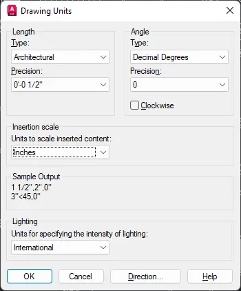
Before you import the PDF make sure you open a blank drawing in AutoCAD and then type UN and press enter.
Now set the unit you want for the imported drawing here in the “Insertion scale” drop-down and set the Precision and Length format.
For this example, I am using Architectural formal with ½” precision and inches as the unit.
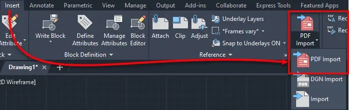
After setting the unit go to the Insert tab and select the PDF import option as shown in the following image:
In the window that opens select the PDF file and click Open.
In the import window, you can select the data types that you want to import in the AutoCAD window from your PDF file.
I would highly recommend you check the “Use PDF layers” option in the layers panel as shown in the following image.
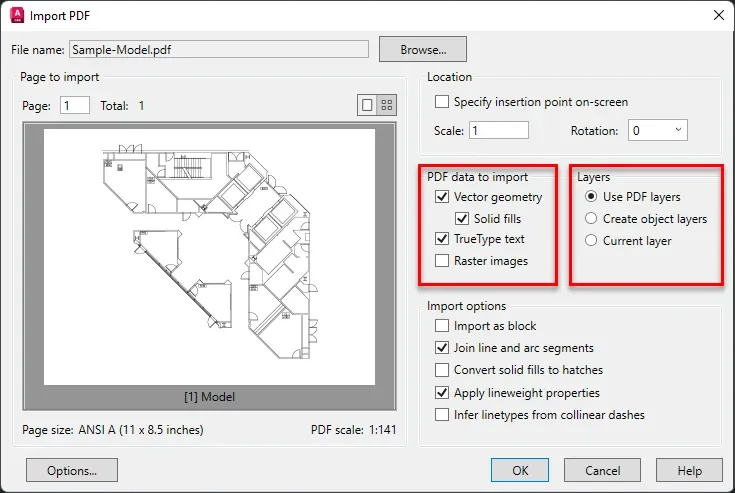
This will import the PDF layers into the AutoCAD file as well and objects will be on the respective layers.
You can also check the “vector geometry” option to import all lines, arcs, circles, ellipses, and Bezier curves as polylines or respective geometry if these geometries are within the tolerance range of the specific geometry.
If they are outside the tolerance range, they are usually added as polylines.
To import solid-filled areas like a 2D solid hatch, wide polylines and Wipeout objects check the “solid fills” option.
If your PDF file is using true type text AutoCAD will recognize it as such and it will import it if you select the “TrueType text” option.
65 lessons| Easy Level
If you are absolute beginner of AutoCAD then you can get started right from scratch using this free course.
The shape font is imported in AutoCAD as geometric objects like lines, polylines or arcs but you can convert it into Mtext using a setting that I have mentioned in the following section.
The “Raster images” option lets you import the raster images from the PDF file, and they are added as an image file in AutoCAD.
You can also select options like “Import as block” from the “Import options” panel to import the entire drawing as a block.
The “Join line and arc segments” option will join all the connected lines, arcs and other segments into one single polyline.
“Convert solid fills to hatches” will convert 2D solid-filled objects into hatches.
To insert the geometries with line weight properties, keep the “Apply linewidth properties” option checked.
“Infer line types from collinear dashes” will let you import the line types as one continuous polyline with a dashed line type assigned to it.
When you are done making your preferred settings in the “import PDF” window click OK, and the PDF file will be added as a DWG object.
After inserting you can check the scale of the added PDF and resize it using the scale command as shown in the following example.
After adding the drawing, the first step is making sure the added drawing is correct to scale.
To set the scale properly I will use the Scale command with the Reference option.
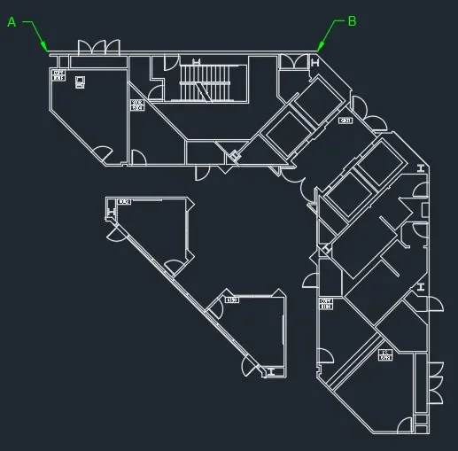
In the example drawing as shown in the following image the distance between points A and B is 57’5”.
Select the Scale command from Modify panel of the home tab or type SC and press enter to start the scale command.
Select the entire set of objects and press enter key.
Now select point A as the base point and then select the reference option from the command line as shown in the following image.

Now click on point A and then on point B and then type 57’5” on the command line and press enter key.
This will change the length of line AB to 57’5” and change everything else in the drawing proportionally.
The next step after scaling our drawing is converting the text that is added as geometry into an actual text format.
The text is added in the drawing file as Mtext if you’ve created it using true type font but if the PDF contains shape font, then it is added as geometry like line, arc and polyline.
To convert the shape (SHX) font into actual text you can use the “Recognize SHX text” option.
To do that select the text from the imported AutoCAD drawing and click on the “Recognize SHX Text” option from the “Import” panel of the Insert tab as shown in the image below.
The text in the form of geometry will be converted into Mtext.
If, however, the “Recognize SHX Text” option is not able to convert the text into Mtext then select smaller pieces of text like a few words and then try the command a few times.
Text in vertical orientation is hard to convert and you may need to make the text horizontal before converting it into Mtext.
To make the text recognition settings better you can click on the “Recognition settings” option which is right underneath the “Recognize SHX Text” option on the Import panel of the Insert tab as shown in the image above.
A “PDF Text Recognition Settings” window will open where you can click multiple fonts from the list to allow AutoCAD to compare the geometry with multiple Shape fonts.

You can also decrease the Recognition threshold slider to a lower value to allow loosely similar texts to match and thereby increasing the chances of converting geometry into text.
Click OK after making these changes in the PDF Text Recognition Settings window and once again try converting geometry into text using Recognize SHX Text option.
If your PDF file is just a simple image made with pixels like a scan taken from a scanner or a simple image that you clicked using your smartphone, then the method is slightly different.
If you prefer a video instead of this article then watch it here to learn all about converting raster PDFs into AutoCAD files.
This method will also work the same if you want to convert the scanned images into AutoCAD drawings.
In this case, you need to first prepare the file using a free vector software called Inkscape.
If you use Adobe Illustrator, you can use that too but for this example, I will use Inkscape as its open source can free.
After you’ve installed Inkscape you can import the scanned PDF or image directly into the software.
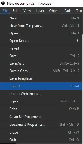
Go to the File menu then select Import and locate the scanned PDF (or image) and then click OK to import it in the Inkscape window as shown in the following image.
Select the imported image and then click on it and it will highlight with a border, simply drag it and drop it on the blank paper.
You can also click on the anchors at the end of the scanned image to scale it and fit it into the paper as shown in the following image.
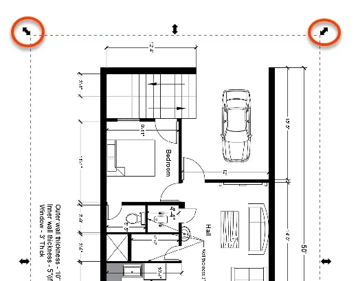
Make sure you press and hold the Ctrl key when scaling the image using anchors to ensure uniform scaling in all directions.
After you’ve scaled the image, you need to ungroup it to make it properly editable in Inkscape.
Simply select the imported image and then right-click and select “Ungroup” from the menu.
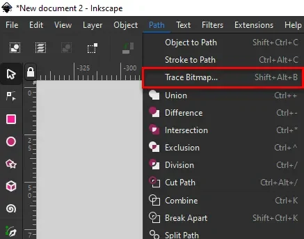
After ungrouping the image keep it selected and then go to the path menu and select Trace Bitmap.
The trace bitmap option will show up and the preview of the image will also show in the preview panel as shown in the following image.
If you don’t see the preview yet, then simply right-click on the image again and select “ungroup” a few times so that you get a preview in the “Trace bitmap” option.
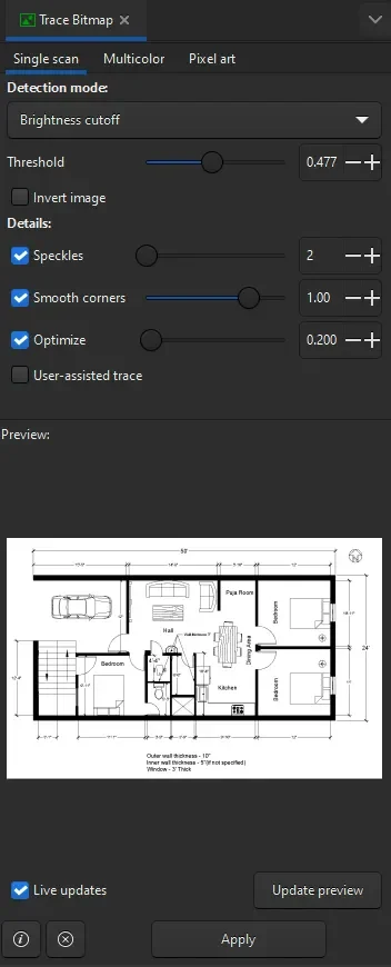
In the Trace Bitmap option select the “Single scan” tab and, in the “detection mode” select “Brightness Cut-off”.
Now change the Threshold value to a higher number to make the lines prominently visible and you can change it to a lower number value to decrease the visibility of lines.
If you want to remove objects like shaded regions, you can move this slider to a lower value and to include more details move it towards the right to a larger value.
In my case, I will keep it somewhere close to 0.5 and click “update preview”.